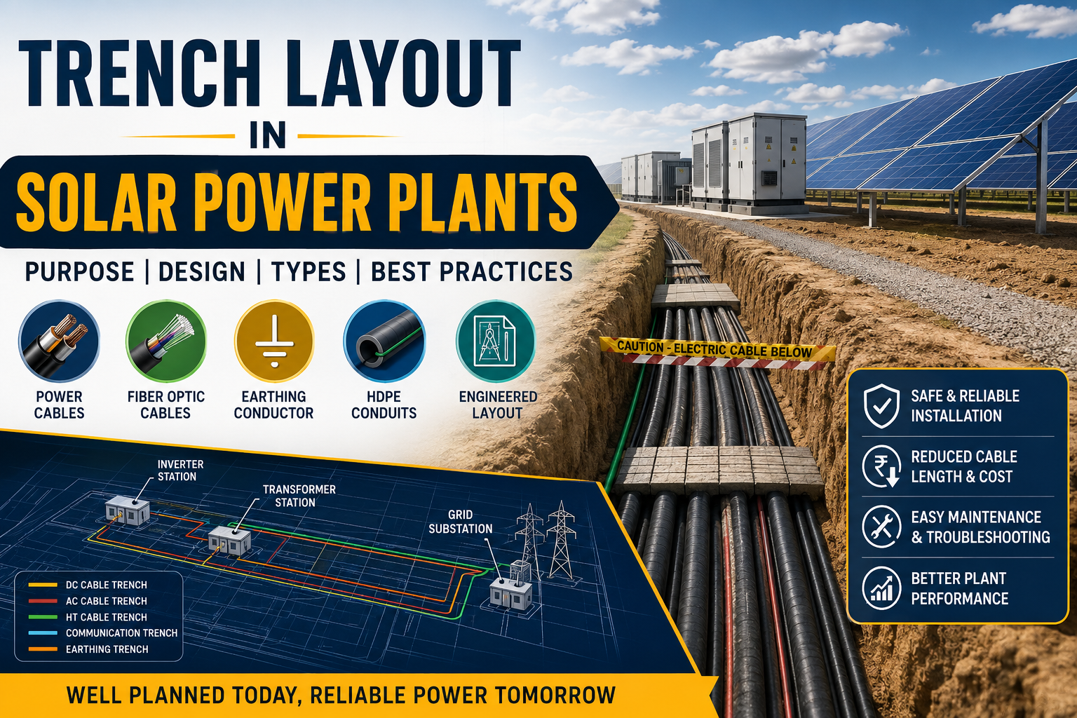
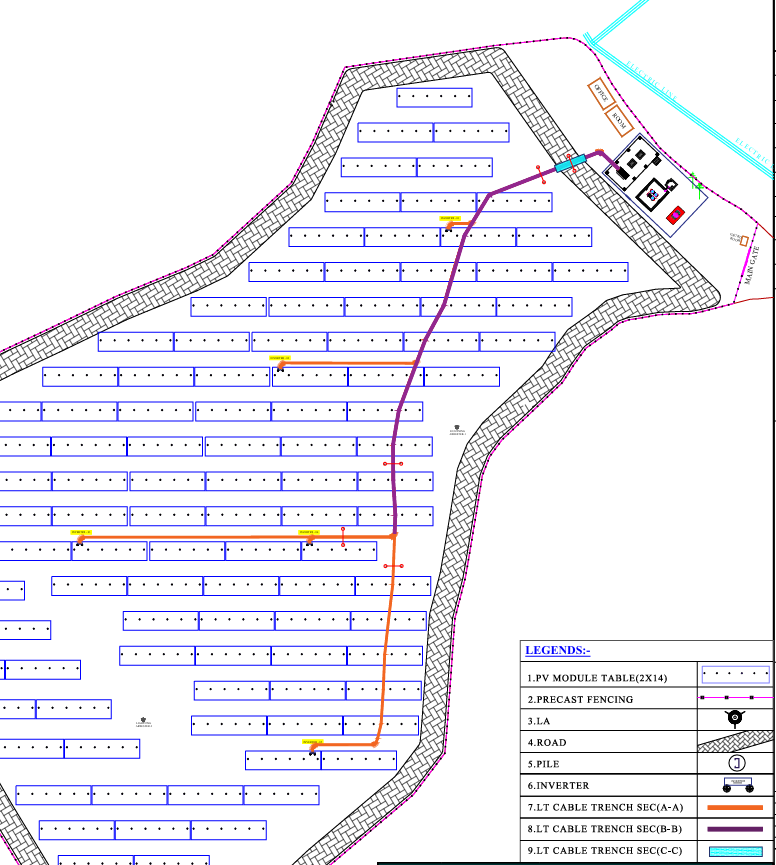
Trench Layout in Solar Power Plants is an essential engineering drawing that defines the underground routing of DC cables, AC cables, communication cables, earthing conductors, and HDPE conduits. A properly designed trench layout improves cable safety, reduces installation costs, simplifies maintenance, and ensures reliable long-term operation of the solar power plant.
It acts as the road map for underground electrical infrastructure, ensuring all cables safely connect PV arrays, inverter stations, transformers, switchgear, and the grid substation.
Without a proper trench layout, cable installation becomes disorganized, costly, and difficult to maintain.
Why is Trench Layout Needed?
A solar power plant may contain tens to hundreds of kilometers of underground cables.
The trench layout helps engineers:
Route cables safely
Reduce cable length
Minimize voltage drop
Avoid cable crossing
Prevent future excavation damage
Improve maintenance
Reduce installation cost
Keep construction organized
Ensure safety standards
Simplify future expansion
Think of it as the road network of a solar power plant—without roads, vehicles cannot move; without trenches, power cannot travel efficiently.
Why Underground Cables Instead of Overhead?
Most modern solar plants prefer underground cabling because it offers:
Underground Trench:
Better appearance
Safer
Less weather impact
Lower maintenance
Better land utilization
More reliable
Overhead Line:
Visible conductors
Higher accidental contact risk
Wind and storms affect lines
More maintenance
Requires poles
Exposed to faults
A single trench may carry several cable types:
1. DC Power Cables PV String → Combiner Box
Combiner Box → Inverter
Voltage:
.1000 V DC
.1500 V DC
2. AC Power CablesType your paragraph here
From: Inverter → LT Panel
LT Panel → Transformer
Transformer → HT Switchgear
Main Components of a Trench Layout Drawing
A trench layout drawing includes:
Cable routing
Trench width
Trench depth
Cable identification
Cable quantity
Junction boxes
Crossing locations
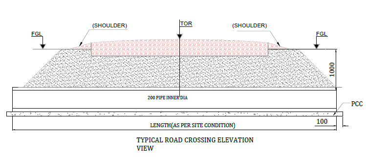
Road crossings
Culvert crossings
Transformer connections
Inverter connections
Array connections
Earthing routes
Fiber routes
Coordinates
Chainage Reference levels
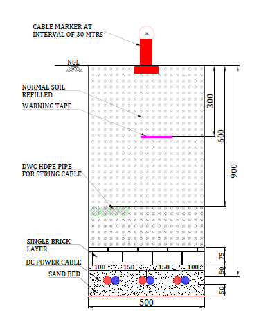
Typical Trench Dimensions:
Cable Type:Dc cable
width:300–450 mm
Depth:600–750 mm
Cable Type:LT AC Cable
width:300–450 mm
Depth:600–750 mm
Cable Type:HT Cable
width:600–900 mm
Depth:900–1200 mm
Cable Type:Earthing
width:300 mm
Depth:600 mm
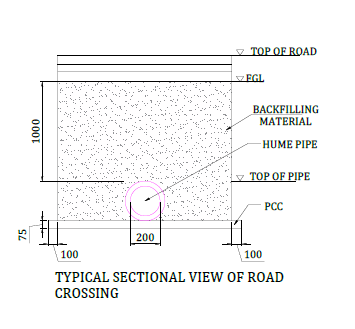
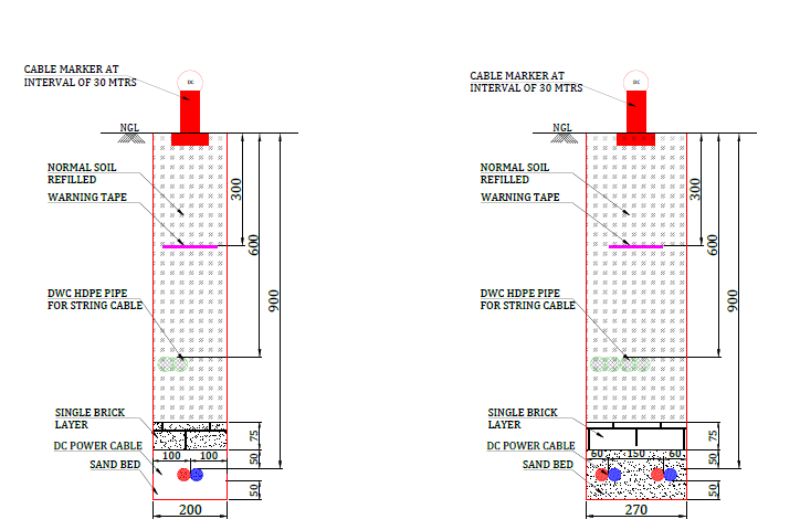
Typical Trench Cross Section:
How Engineers Design a Trench Layout:
Step 1: Study Plant Layout
Review:
Module layout
Inverter layout
Roads
Buildings
Drainage Boundaries
Step 2: Identify Equipment Locations
Locate: Inverters
Transformers
HT panels
SCADA room
Switchyard
Step 3: Select Cable Routes
Aim to:
Minimize cable length
Avoid sharp bends
Avoid future construction areas
Step 4: Calculate Cable Quantity
Determine:
Number of cables
Cable sizes
Spare ducts
Future expansion needs
Step 5: Decide Trench Size
The trench must accommodate:
All cables
Minimum spacing
Sand bedding
Protective covers
Step 6: Prepare Drawings
Include:
Plan view
Cross sections
Cable schedules
Coordinates Notes
Conclusion:
A Trench Layout in Solar Power Plants is far more than just an underground cable routing plan; it is a critical engineering document that ensures the safe, reliable, and efficient transmission of power throughout the entire solar power plant. A well-designed trench layout minimizes cable lengths, reduces voltage drop and power losses, protects cables from mechanical damage, and simplifies future maintenance and expansion activities. Proper planning of trench dimensions, cable separation, HDPE conduits, drainage, earthing conductors, and warning systems helps improve construction quality while ensuring compliance with IEC and IS standards.
During the design stage, engineers must carefully evaluate site conditions, equipment locations, cable quantities, future expansion requirements, and maintenance accessibility before finalizing the trench routing. Following engineering best practices not only reduces installation costs but also improves the long-term reliability, safety, and operational efficiency of the solar power plant. Whether the project is a 1 MW ground-mounted solar plant or a large utility-scale installation, a properly engineered Trench Layout in Solar Power Plants plays a vital role in delivering a high-performance, cost-effective, and reliable renewable energy system for decades.