INTRODUCTION
Save Time on Solar Design — Get the Complete Solar Design CALCULATION WITH AUTOCAD FILES ,Click below for Design Bundle
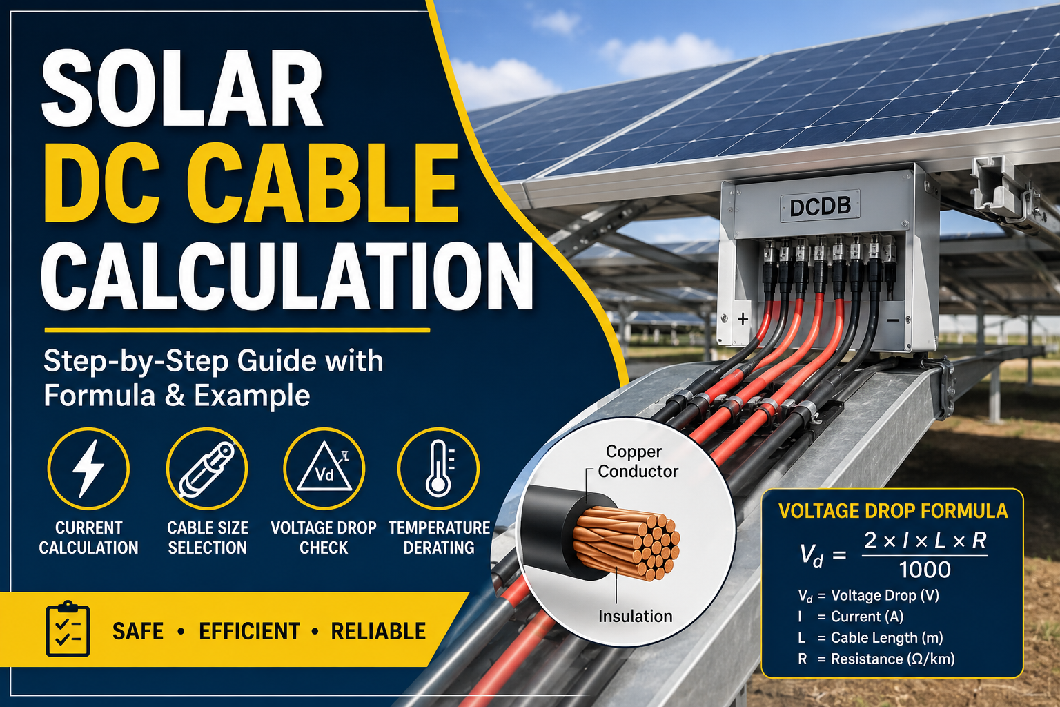
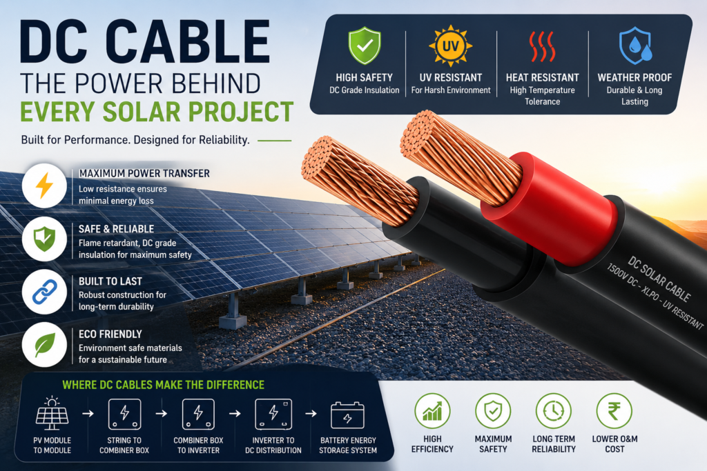
Click hereSolar DC cable calculation is an important part of designing a safe and efficient solar PV system. DC cables carry electrical power from the solar PV modules to string inverters, DC combiner boxes, or other DC equipment, so selecting the correct cable size is essential for reliable system operation.
ParameterValue
Plant Capacity18 MWModule Rating590 WModule
Vmp-42.89 V
Module Imp1-4.45 A
Module Isc-15.21 A
Modules per String-26
Maximum Strings per SMB-21
Cable TypeCu XLPO Solar CableSystem Voltage-1500 V DC
Ste p 1– Calculate Full Load CurrentThe current flowing from the strings into the SMB is:
Full Load Current = Number of Strings × Module Imp
Using our project:
Full Load Current = 2 × 14.45 = 28.896 A
Therefore,Design Current = 28.896 AThis current will be used in the remaining calculations.
Step 2 – Short Circuit Withstand CalculationSuppose a fault occurs
.The cable should not melt before the protection device disconnects the fault.
According to IEC standards, the required conductor area is calculated using:
A = (Isc × √t) / K
Where: Isc = 30.43 A(15.21X2),Two strings are connected in parallel using a Y-Connector
Fault Duration = 1 second
Copper Constant K = 143
Substituting the values:
A = (30.43 × 1) / 143A = 0.2128 mm²
Although the minimum theoretical requirement is only 0.2128 mm², this does not mean a 1 mm² cable can be used.The cable must still satisfy current carrying capacity and voltage drop requirements.
Step 3 – Current Carrying Capacity
The cable should continuously carry load current without exceeding its permissible conductor temperature.
However, cable ratings provided by manufacturers are valid only under standard conditions.
Actual site conditions require derating.
For this project, the following derating factors were considered:
Ground Temperature = 35°C
Cable Grouping = 12
cables Soil Thermal Resistivity = 1.5 K·m/W
Buried InstallationThe combined derating factor becomes:0.534
Therefore,Required Current Capacity= 28.9 ÷ 0.534= 54.11 A
The selected 6 mm² Cu XLPO Solar Cable has a current carrying capacity of 70 A, which is higher than the required 54.11 A.Hence, it satisfies the ampacity requirement.
Step 4 – Voltage Drop Calculation
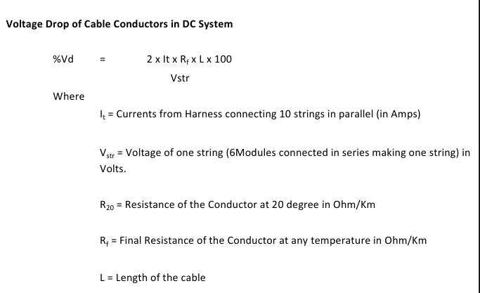
Next, verify that voltage loss remains within acceptable limits.
Project Data:
Current = 28.896 A
Cable Length = 65 m
Cable Resistance = 3.39 Ω/km
Operating Temperature = 50°C
After temperature correction, the resistance becomes:4.056 Ω/km
The calculated voltage drop is:7.62 VPercentage voltage drop:0.68%Since this is below the commonly accepted design limit, the selected cable is acceptable.
Step 5 – Power Loss
Every cable has resistance, so some energy is lost as heat.
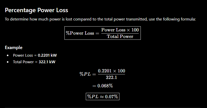
Power Loss:0.2201 kW
Percentage Power Loss:0.07%
This confirms that the selected cable provides excellent efficiency with negligible energy loss.
CONCLUSION:
DC cable sizing is not just a mathematical calculation—it is a critical engineering process that directly impacts the safety, efficiency, and long-term performance of a solar PV system. By considering short-circuit withstand capacity, current carrying capacity, voltage drop, and power loss together, engineers can confidently select the most suitable cable for any solar installation.If you're a solar design engineer or EPC professional, mastering DC cable sizing will help you design safer, more efficient, and standards-compliant solar projects.
Solar DC cable calculation is an essential part of solar PV system design to ensure safe, reliable, and efficient power transmission from the PV modules to the inverter. The correct cable size should be selected by considering current-carrying capacity, cable length, voltage drop, power loss, temperature, cable grouping, installation conditions, and short-circuit withstand capability.
A properly sized DC cable helps minimize energy losses, maintain system performance, and prevent overheating or cable failure. Therefore, a complete solar DC cable calculation should be performed before finalizing the cable size and installation arrangement for any solar PV project.
A properly sized DC cable reduces power losses, voltage drop, and overheating, ensuring safe and efficient operation of the solar PV system throughout its service life.
Save Time on Solar Design — Get the Complete Solar Design CALCULATION WITH AUTOCAD FILES ,Click below for Design Bundle
Click here