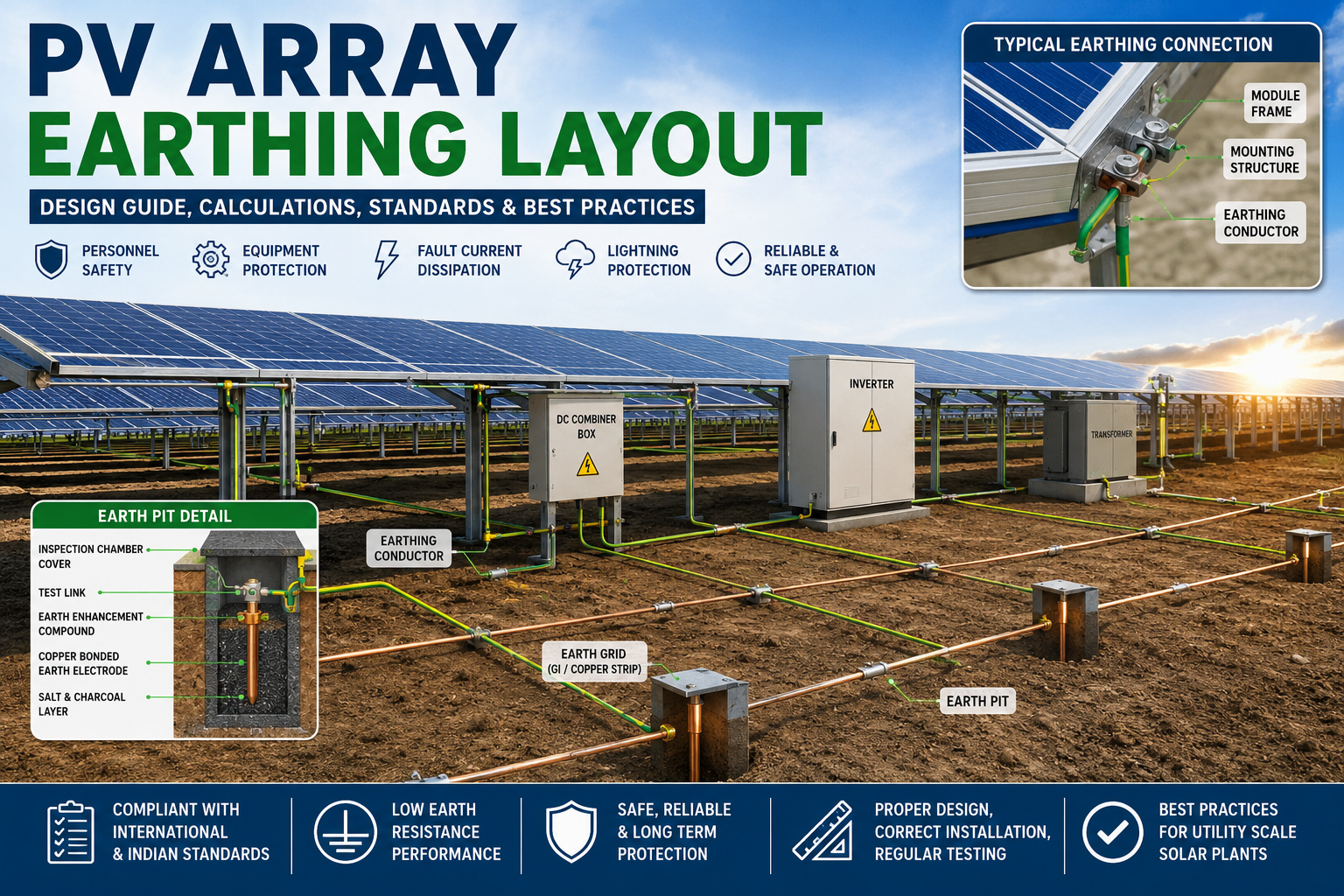
PV Array Earthing Layout in Solar Power Plants is an essential part of electrical safety and equipment protection. A properly designed earthing system provides a low-resistance path for fault currents, helps protect solar modules, mounting structures, inverters, and other electrical equipment, and reduces the risk associated with lightning and electrical faults.
A well-designed PV Array Earthing Layout in Solar Power Plants helps maintain safe operation throughout the project's life. The earthing system should be designed according to the plant capacity, soil conditions, fault current levels, equipment requirements, applicable standards, and site-specific conditions.
This article explains the purpose, components, design methodology, calculations, applicable standards, installation practices, and common mistakes in PV array earthing layouts.
What is PV Array Earthing?
PV array earthing is the process of electrically connecting all exposed metallic parts of a solar photovoltaic installation to the earth through a low-resistance grounding network.
The metallic structures themselves do not normally carry current. However, due to insulation failure, damaged cables, lightning strikes, or accidental contact with live conductors, dangerous voltages can appear on these structures. Earthing safely diverts these fault currents into the ground.
The following components are normally connected to the earthing network:
Module mounting structures
Module frames (where required by manufacturer)
Tracker structures
DC combiner boxes
String combiner boxes
Junction boxes
Inverter body
Transformer body
HT panel
ACDB
CDB
Cable trays
Metallic fencing (when required)
Lightning protection system
Why is PV Array Earthing Important?
Without an effective grounding system, a solar plant may experience:
Electric shock hazards
Equipment damage
Fire hazards
Frequent inverter faults
Communication failures
Increased lightning damage
Reduced system reliability Non-compliance with electrical standardsProper earthing significantly improves the long-term safety and availability of the solar power plant.
Objectives of PV Array Earthing
The main objectives are:
Protect personnel from electric shock
Dissipate fault current safely
Maintain equipment at earth potential
Reduce lightning damage
Protect sensitive electronics
Improve inverter performance
Ensure statutory compliance
Increase system reliability
Components of a PV Array Earthing System
A complete PV array grounding system generally consists of the following components.
1. Earth Electrode
The earth electrode transfers electrical current into the surrounding soil.
Common types include:
Copper-bonded rod
GI pipe electrode
Copper plate electrode
Chemical earthing electrode
Utility-scale solar plants generally use copper-bonded or chemical electrodes because they provide lower resistance and longer service life.
2. Earthing Conductor
The grounding conductor connects all equipment to the earth grid.
Common materials include:
Bare copper
Copper strip
GI strip
Copper cable
Aluminum conductor (specific applications)
Typical sizes include:
25×3 mm GI strip
50×6 mm GI strip
35 mm² Copper
70 mm² Copper
Actual conductor size depends upon fault current calculations.
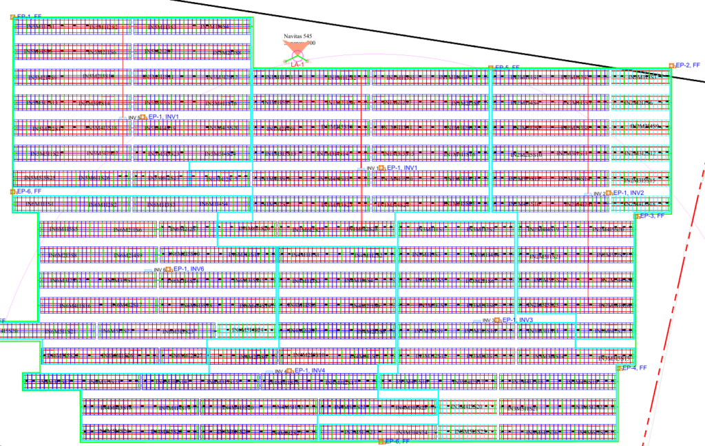
3. Earth Grid
The earth grid forms the backbone of the entire grounding system.
It consists of buried conductors interconnected throughout the plant.
The grid:
Equalizes ground potential
Reduces touch voltage
Reduces step voltage
Improves fault current dissipation
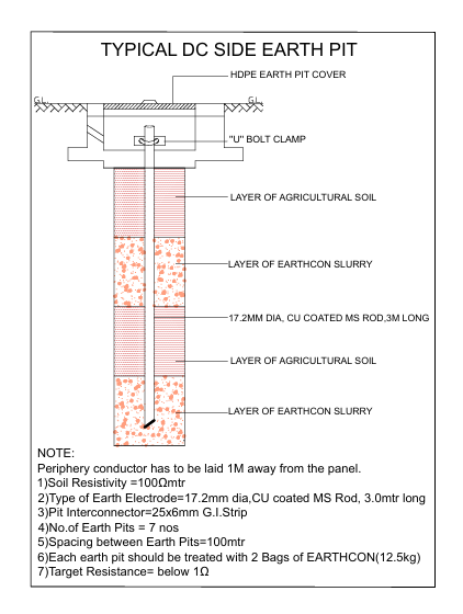
4. Earth Pit
Each earth pit consists of:
Earth electrode
Inspection chamber
Test link
Earth enhancement compound
Watering arrangement (if required)
Types of Earthing in Solar Plants
Although commonly referred to as "earthing," a solar plant typically includes several distinct grounding systems:
1.Equipment Earthing – Metallic frames, structures, inverter enclosures, transformers, cable trays, and support structures.
2.System Earthing – Neutral grounding for transformers and generators (where applicable).
3.Lightning Earthing – Dedicated grounding for lightning arresters and masts.
4.Functional Earthing – Earthing for communication systems, SCADA, and sensitive electronics.These systems may be interconnected or separated based on project specifications and applicable standards.
These systems may be interconnected or separated based on project specifications and applicable standards.
The effectiveness of the earthing system depends on several parameters:
Soil resistivity
Soil moisture content
Soil temperature
Fault current magnitude
Grid geometry
Burial depth
Electrode spacing
Conductor material
Corrosion resistance
Seasonal variation
High-resistivity soils generally require more electrodes, larger grids, or chemical enhancement materials to achieve the target resistance.
Recommended Standards
Common international and Indian standards include:
IEC 60364
IEC 62548
IEC 62305 (Lightning Protection)
IEEE Std 80 (Substation Grounding)
IEEE Std 81 (Soil Resistivity Measurement)
IS 3043 (Code of Practice for Earthing)
NEC Article 690 (PV Systems)
Always verify the standards required by your utility, client, or jurisdiction
1 thought on “PV Array Earthing Layout in Solar Power Plants: Design Guide, Calculations, Standards, and Best Practices”