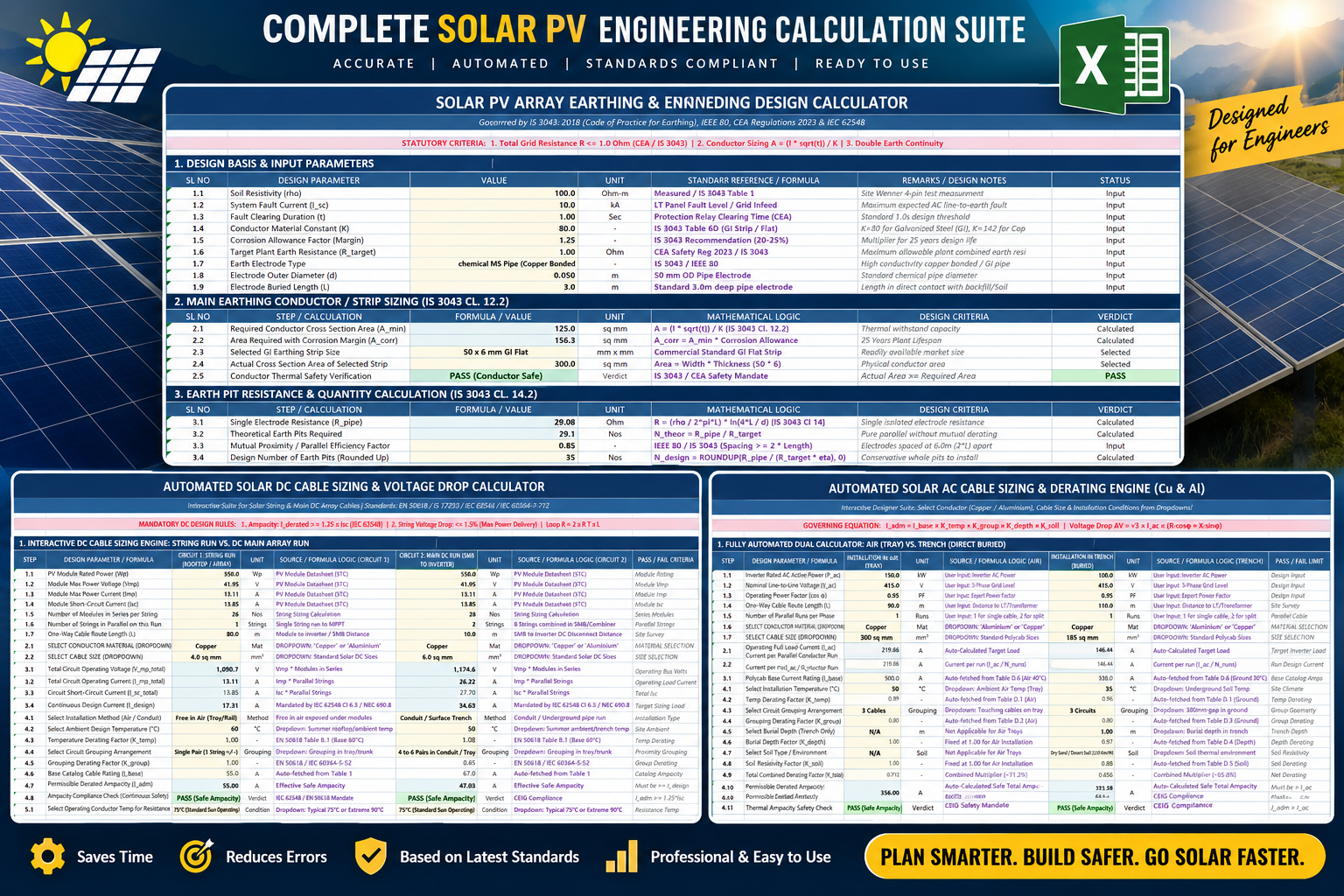
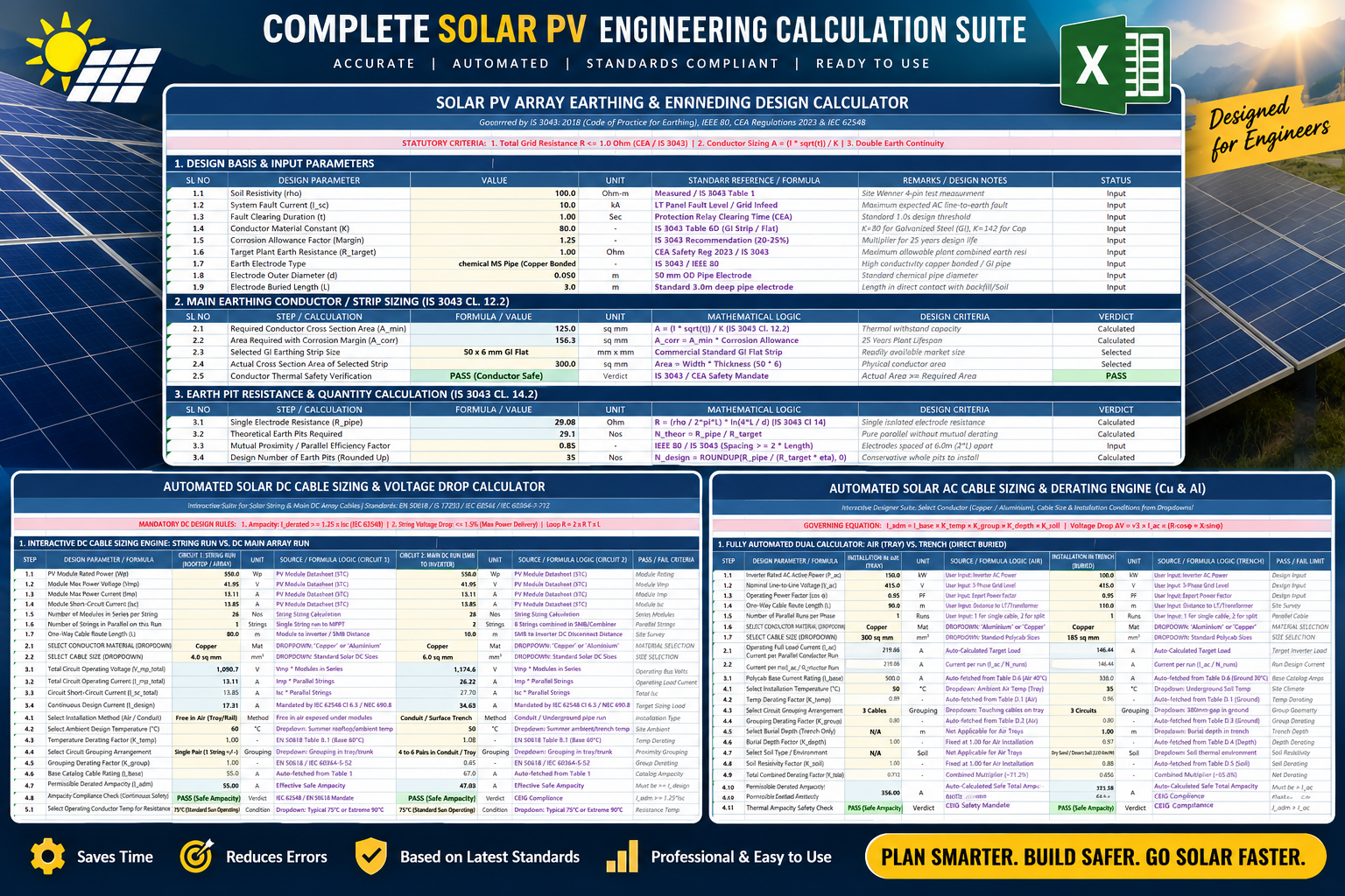
Save Time on Solar Design — Get the Complete Solar Design CALCULATION WITH AUTOCAD FILES ,Click below for Design Bundle
Introduction:
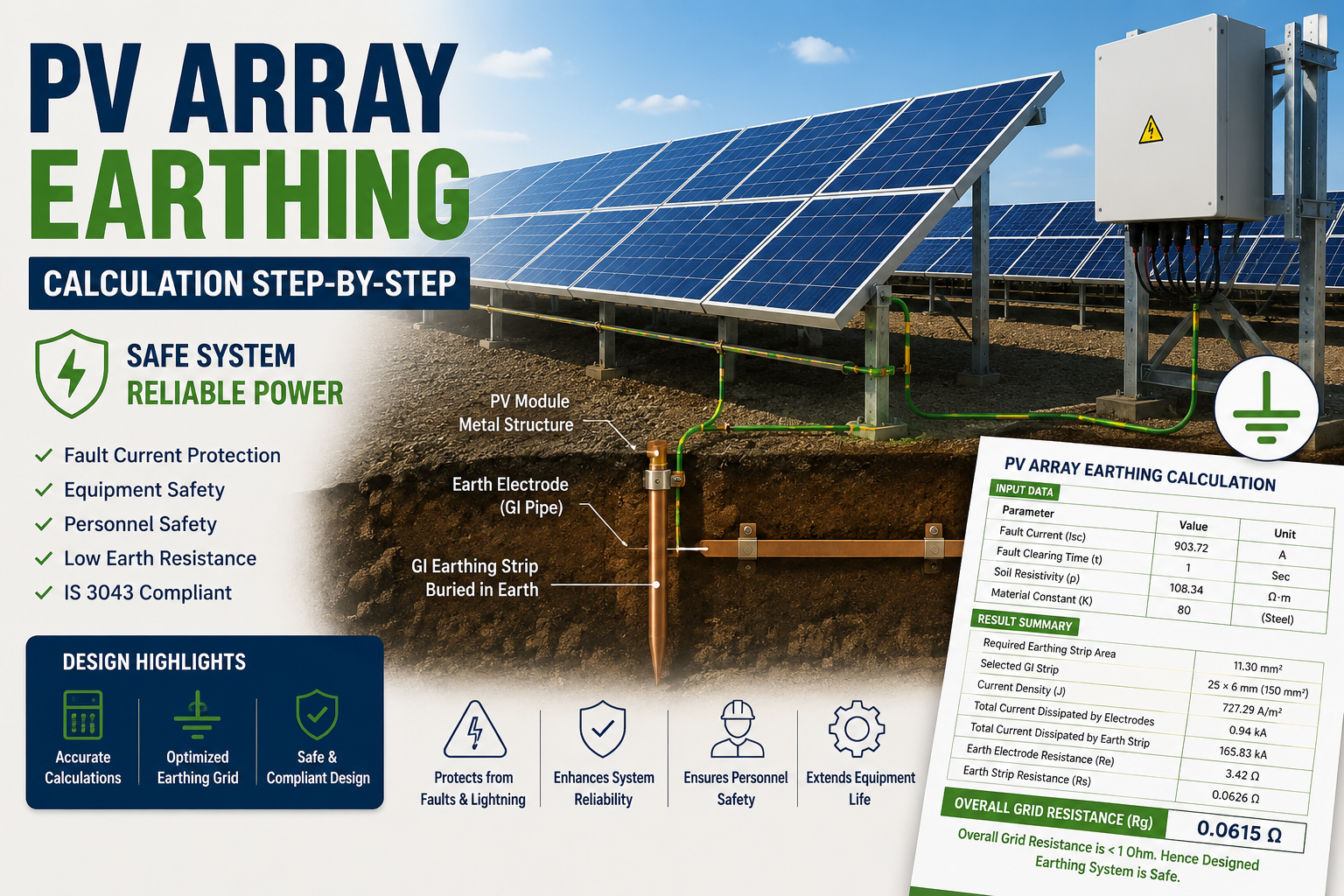
PV Array Earthing Calculation is an essential part of solar PV plant electrical design because it ensures that metallic structures, module frames, inverter stations, and other exposed conductive equipment remain safely grounded. A properly designed earthing system provides a low-resistance path for fault current and helps protect personnel and equipment during electrical faults, insulation failures, and lightning events.
The objective of PV array earthing design is to:
Protect human life from electric shock
Dissipate fault current safely
Protect equipment against damage
Maintain touch and step voltage within permissible limits
Achieve earth resistance below the project requirement (generally less than 1 Ω)
This article explains the complete design methodology of PV array earthing using IS 3043 – Code of Practice for Earthing with a solved example.
PV Array Earthing Calculation Method
PV Array Earthing Calculation
The PV Array Earthing Calculation is performed by considering the fault current, fault clearing time, soil resistivity, conductor material, and required earthing arrangement.
Design DataBefore starting any earthing calculation, collect the following project data.
Parameter:
Fault Current (Isc) for DC System-903.72 -ISC CONSIDERD OF ONE INVERTER (71STRING X13.29 A ISC OF MODULE)
Operation Time of disconnecting device (t) -1 Second
Soil Resistivity (ρ)-108.34 Ω·
Factor dependent upon the material (K)-80-As per table 6A of IS 3043 for steel
These values are taken from the design calculation sheet.
Step 1 – Selection of Earthing Strip
The first step is selecting the minimum conductor cross-sectional area.
According to IS 3043,
A=I×√T/K
Where
A = Required conductor area (mm²)
I = Fault Current (A)
t = Fault duration (sec)
K = Material constant
Calculation
Given,
I = 903.72
At = 1 sec
K = 80
Therefore,
A=903.72×√T/80A=11.30mm2
Therefore,
Required conductor area = 11.30 mm²
Since corrosion allowance is considered zero in this design,
Required Area=11.30 mm²
Selection of GI Strip,
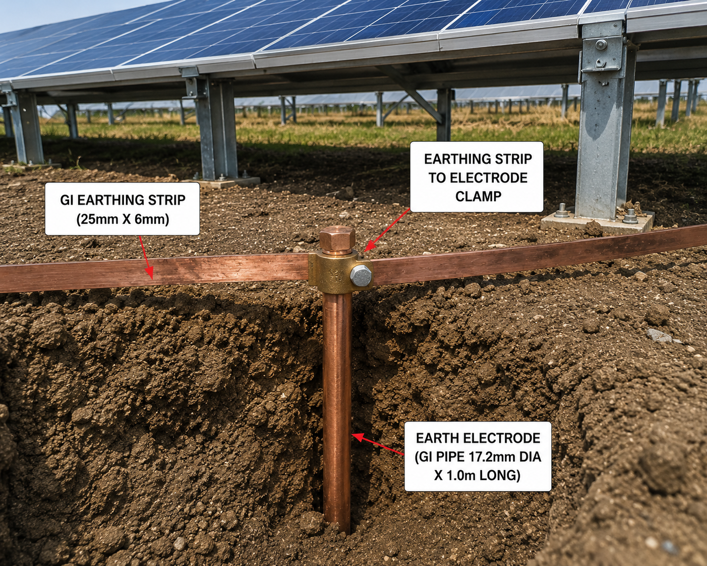
A standard strip selected is 25 mm × 6 mm
Cross-sectional area 25×6=150 mm2
Available Area=150 mm²
Since,
150 mm² > 11.30 mm²
Hence the selected GI strip is safe.
Step 2 – Current Density Calculation
The next step is checking how much current can safely dissipate through soil.
Formula
J=7.57×10^√3/√pt
Where
J = Current Density
ρ = Soil Resistivity
t = Fault Duration
Calculation
ρ =108.34 Ω·m
Fault Duration t =1 sec
Therefore,
J=7570/√108.34
J=727.29A/m2
Current Density=727.29 A/m²
Step 3 – Current Dissipated by Earth Electrode
Assume,
Electrode Diameter =17.2 mm
Electrode Length =1000 mm
Surface Area of One Electrode
FormulaA=2πrh.
Wherer = Radius
h = Electrode Length
Calculated Surface Area,
A=0.0540 m2
Current dissipated by one electrode
I=J×A
I=727.29x0.054
I=727.29X0.054
I=39.28A
If 24 electrodes are installed
Total Current
=39.28×24≈0.94 kA
Step 4 - Current dissipated by Earth Strip
Besides electrodes, the buried GI strip also carries fault current.
Surface Area of one metre strip
2(WT+LT+LW)
L=1m
W=0.025 m
T=0.006m
Calculated Surface Area0.0623 m²Current per metre
I=J×A
727.29×0.0623
45.31A
Total strip length
3660 mTotal Current Capacity
45.31×3660
165.83KA
This shows that the buried earth strip carries much higher current than the fault current, providing a significant safety margin.
Step 5 – Earth Electrode Resistance
The resistance of a single rod electrode is calculated using IS 3043.
Formula,
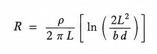
Where
ρ = Soil Resistivity
l = Electrode Length
d = Electrode Diameter
Calculated Result
Single Electrode Resistance
82.05 Ω
For 24 electrodes,
Re=Rr/N
Re=82.05/24
Re=3.42Ω
Step 6 – Earth Strip Resistance
Rs=100ρln(4L/T)/ 2πL
Rs=0.0626Ω
Step 7 – Overall Grid Resistance
Both electrode resistance and strip resistance act in parallel.
FormulaRg=(1/Rs+1/Re)^-1
=(1/0.0626+1/3.42)^-1
Rg=0.0615Ω
0.0615<1Ω
The designed PV array earthing system satisfies the design requirement and is considered safe.
Important Design Considerations
Follow IS 3043 for earthing conductor sizing and resistance calculations.
Measure actual soil resistivity using the Wenner four-pin method before finalizing the design.
Use hot-dip galvanized (GI) materials with adequate corrosion protection and power.
Bond all module mounting structures, inverter frames, combiner boxes, and metallic equipment to the earth grid.
Aim for an overall earth grid resistance below 1 Ω for utility-scale solar plants (or as specified by the project).
click below for pv array earthing layout
Conclusion
A properly designed PV Array Earthing Calculation system is essential for ensuring the safety and reliability of a solar power plant. By selecting the correct conductor size, verifying current dissipation capacity, calculating electrode and strip resistance, and confirming that the overall grid resistance is well below the specified limit, engineers can design an earthing system that complies with IS 3043 and effectively protects both personnel and equipment. In this example, the final earth grid resistance of 0.0615 Ω demonstrates a robust and reliable design with a substantial safety margin.
Save Time on Solar Design — Get the Complete Solar Design CALCULATION WITH AUTOCAD FILES ,Click below for Design Bundle
1 thought on “PV Array Earthing Calculation – 7-Step Guide with Solved Example”