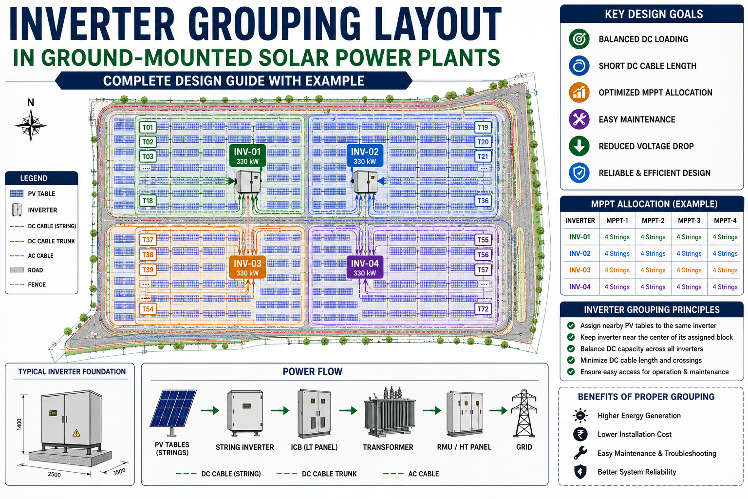
One of the most important engineering drawings in a utility-scale solar power plant is the Inverter Grouping Layout. While the array layout determines where the PV tables are installed, the inverter grouping layout defines which PV tables are connected to each inverter
A well-planned inverter grouping layout reduces DC cable length, balances inverter loading, simplifies construction, improves maintenance, and enhances the overall performance of the solar power plant.
In this guide, we'll explain everything you need to know about designing an inverter grouping layout for a ground-mounted solar project.
What Is an Inverter Grouping Layout?
An inverter grouping layout is an engineering drawing that divides the entire solar plant into individual inverter blocks.
Each inverter block consists of:
A dedicated string inverter
Assigned PV tables
Associated strings
MPPT allocation
DC cable routing
This drawing acts as the bridge between the Array Layout and the String Layout.
Why Is an Inverter Grouping Layout Important?
Without proper grouping, a solar plant can suffer from:
Long DC cable runs
Higher voltage dropIncreased cable cost
Uneven inverter loading
Difficult maintenance
Complicated commissioning
A properly designed inverter grouping layout ensures that every inverter operates efficiently while minimizing overall installation costs.
Information Required Before Preparing an Inverter Grouping Layout
Before creating the layout, the following engineering inputs should be finalized:
1.Approved Array LayoutThe array layout provides:
PV table locations
Table numbering
Module orientation
Number of tables
This serves as the foundation for inverter grouping.
2. Inverter Datasheet
Important information includes:
Rated AC power
Maximum DC voltage
MPPT operating range
Number of MPPTs
Maximum strings per MPPT
Maximum DC input current
These values determine how many PV tables can be assigned to each inverter.
3. Module Specifications
Engineers should verify:
Module power
Voc
Vmp
Isc
Temperature coefficient
These values are required for string sizing and inverter loading.
4. Site Topography
The topographical survey helps identify:
Slopes
Low-lying areas
Roads
Drainage channels
Construction constraints
The inverter grouping should avoid difficult terrain whenever possible.
Design Objectives
The main objectives of inverter grouping are:
Reduce DC cable length
Balance inverter loading
Minimize voltage drop
Simplify string routing
Improve maintenance accessReduce installation costs
Step-by-Step Inverter Grouping Design
Step 1 – Calculate the Number of Inverters
Determine the required number of inverters based on:
Plant DC capacity
Selected DC/AC ratio
Inverter AC rating
Example:Plant DC Capacity = 1.32 MWp
Inverter Rating = 330 kW
Required Inverters = 4
Step 2 – Divide the Plant into Inverter Blocks
Split the PV array into logical blocks.
Each inverter should serve a compact group of nearby PV tables rather than scattered locations.
Compact grouping reduces cable length and simplifies installation.
Step 3 – Place the String Inverter
The string inverter should be positioned:Close to the centre of its assigned PV tablesAway from drainage channelsAbove flood-prone areasAccessible from maintenance roadsWith sufficient working clearanceKeeping the inverter near the PV tables minimizes DC cable length and voltage drop.
Step 4 – Assign PV Tables
Assign nearby PV tables to the same inverter.
Avoid crossing cables between inverter blocks.
Typical assignment example:
Inverter INV-01 → Tables T01 to T18
Inverter INV-02 → Tables T19 to T36
Inverter INV-03 → Tables T37 to T54
Inverter INV-04 → Tables T55 to T72
This organized approach simplifies construction and maintenance.
Step 5 – Balance the Load
Every inverter should receive approximately equal DC capacity.
Balanced loading improves inverter utilization and ensures consistent energy production across the plant.
Step 6 – Plan MPPT Allocation
Distribute strings evenly across the available MPPTs.
Example:
MPPT-1 → 4 Strings
MPPT-2 → 4 Strings
MPPT-3 → 4 Strings
MPPT-4 → 4 Strings
Balanced MPPT allocation maximizes energy harvesting.
Step 7 – Optimize Cable Routing
The DC cable route should be:
Short
Straight
Easy to identify
Free from unnecessary crossings
Organized cable routing reduces installation time and future maintenance effort.
Conclusion
The inverter grouping layout is one of the key engineering drawings in a ground-mounted solar power plant. It defines the relationship between PV tables and string inverters, ensuring that each inverter operates efficiently while minimizing cable costs and simplifying construction.
By carefully planning inverter blocks, balancing the DC load, optimizing MPPT allocation, and positioning inverters close to their assigned PV tables, engineers can improve plant performance, reduce project costs, and create a cleaner, more maintainable design.
A well-prepared inverter grouping layout also serves as the foundation for the string layout, cable routing, trench design, and overall electrical coordination, making it an essential part of every utility-scale solar project.