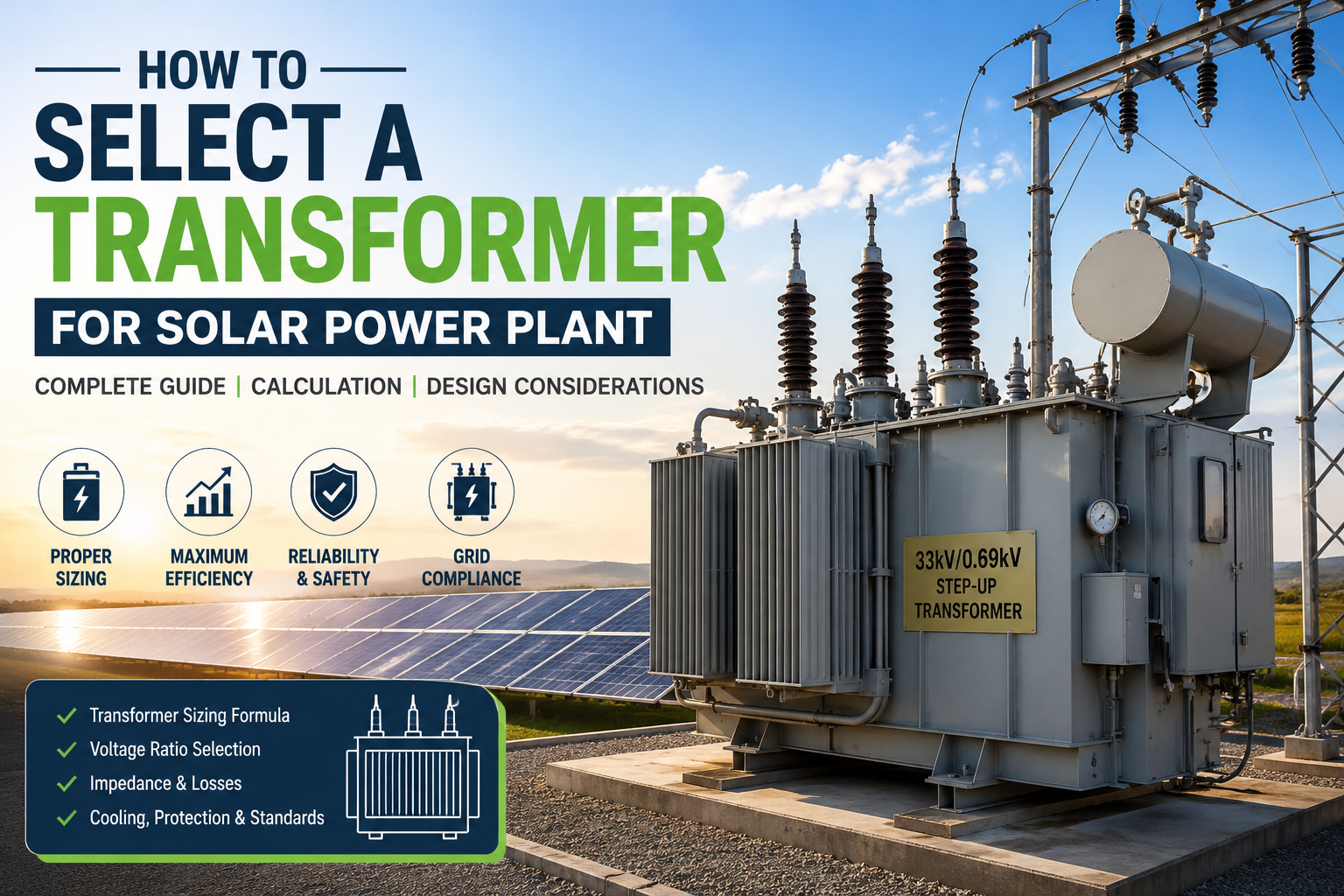
How to Select a Transformer for a Solar Power Plant is an important design decision because the transformer must efficiently transfer electrical energy from the inverter output voltage to the grid voltage. Selecting the correct transformer rating, voltage ratio, impedance, cooling method, and protection system is essential for reliable and efficient solar power plant operation.
How to Select a Transformer for a Solar Power Plant depends on several factors, including the inverter output voltage, grid voltage, plant capacity, load requirements, transformer rating, impedance, losses, environmental conditions, and applicable electrical standards.
Before selecting a transformer, the design engineer must collect several key parameters related to the project. The most important consideration is the AC export capacity of the plant rather than the installed DC capacity. This is one of the most common mistakes made by beginners in solar design. For example, a solar plant may have an installed capacity of 5.4 MWp on the DC side while the inverter output is limited to 4 MW AC. Since the transformer is connected to the inverter output, it only carries the AC power delivered by the inverter. Therefore, the transformer rating must always be based on the maximum AC export capacity instead of the total DC capacity of the photovoltaic modules.
The transformer rating is generally determined using the apparent power requirement of the system. Since transformers are rated in kVA or MVA rather than kilowatts, the real power must first be converted into apparent power by considering the operating power factor. The relationship is expressed by the equation :
S= P/PF
where:S = Apparent Power (kVA)
P = Real Power (kW)
PF = Power Factor
Suppose a solar power plant exports 4000 kW at a power factor of 0.99. The required transformer capacity is calculated as follows:
S=40000/0.99=4040 KVA
Although the calculated requirement is approximately 4.04 MVA, engineers generally do not select a transformer with exactly the calculated value. Instead, the next higher standard rating is chosen to provide adequate thermal margin, accommodate reactive power variations, and allow for future operating conditions. In this case, a 5 MVA transformer would normally be selected. Choosing a transformer with a higher standard rating also reduces the risk of continuous overloading and improves long-term reliability.
Voltage ratio is another important factor in transformer selection. The transformer must match both the inverter output voltage and the utility grid voltage. For instance, if the inverter output is 690 V and the utility network operates at 33 kV, the transformer should have a voltage ratio of 690 V / 33 kV. Similarly, if the inverter operates at 800 V, an 800 V / 33 kV transformer is selected. Selecting the wrong voltage ratio can lead to improper voltage regulation, increased losses, or non-compliance with utility interconnection requirements. Therefore, the final voltage ratio should always be confirmed with the inverter manufacturer and the local utility specifications.
Apart from capacity and voltage ratio, transformer impedance plays a significant role in determining system performance. Impedance limits the fault current during short-circuit conditions and affects voltage regulation under varying load conditions. In solar power plants, transformer impedance typically ranges between 5% and 8%, depending on the project requirements. A lower impedance results in better voltage regulation but allows higher fault currents, whereas higher impedance reduces fault current at the expense of increased voltage drop. The final impedance value is generally specified after coordination studies involving the transformer, switchgear, protection system, and utility requirements.
Transformer losses must also be evaluated carefully because they directly affect the overall energy yield of the solar power plant. Two major categories of losses occur within a transformer: no-load losses and load losses. No-load losses, also known as core losses, occur whenever the transformer is energized regardless of the connected load. These losses are primarily caused by hysteresis and eddy currents within the magnetic core. Load losses, often referred to as copper losses, occur due to the resistance of the transformer windings and increase with the square of the load current. Since solar power plants operate for more than twenty years, even a small reduction in transformer losses can result in substantial energy savings over the plant's lifetime. Consequently, project developers often prefer transformers with lower guaranteed losses despite their slightly higher initial cost.
The cooling method of the transformer should also be selected based on the operating environment and loading conditions. Most solar power plants use ONAN (Oil Natural Air Natural) cooling, where the transformer oil circulates naturally and heat is dissipated through the surrounding air without the assistance of external fans. For larger transformers subjected to higher loading, ONAF (Oil Natural Air Forced) cooling is often adopted. In this arrangement, cooling fans provide additional heat dissipation, allowing the transformer to deliver greater output without exceeding permissible temperature limits. The selection of the cooling method depends on transformer capacity, ambient temperature, site conditions, and expected loading profile.
Another essential parameter is the transformer vector group. The vector group defines the phase relationship between the primary and secondary windings as well as the winding configuration. In most solar power applications, Dyn11 is widely preferred because it provides a delta connection on the high-voltage side and a star connection with neutral on the low-voltage side while introducing a 30-degree phase shift. This configuration helps suppress third harmonic currents, provides a stable neutral point for grounding, and offers better compatibility with modern inverter-based generation systems. Nevertheless, the final vector group should always comply with the utility interconnection standards and system protection requirements.
Modern solar transformers are also equipped with tap changers to compensate for voltage variations. Depending on the project requirements, either an Off-Circuit Tap Changer (OCTC) or an On-Load Tap Changer (OLTC) may be selected. Smaller inverter-duty transformers generally use off-circuit tap changers because voltage adjustments are infrequent and can be performed only when the transformer is de-energized. Large grid-interfacing power transformers often incorporate on-load tap changers, allowing voltage regulation without interrupting power delivery. Typical tap ranges include ±5% or ±10% in discrete steps, enabling the transformer to maintain the required voltage under varying grid conditions.
Protection is another crucial consideration during transformer selection. Since the transformer is one of the most expensive assets in a solar power plant, adequate protection is essential to ensure long service life and reliable operation. Large oil-filled transformers are commonly provided with Buchholz relays, pressure relief devices, winding temperature indicators, oil temperature indicators, differential protection, restricted earth fault protection, overcurrent protection, earth fault protection, and surge arresters. The protection scheme should be coordinated with the switchgear, relays, inverter protection functions, and utility requirements to ensure selective fault clearance without unnecessary interruptions.
Environmental conditions also influence transformer selection. High ambient temperatures, dusty environments, high altitudes, and coastal installations can significantly affect transformer performance. Manufacturers apply appropriate derating factors when transformers are installed in locations where the ambient temperature exceeds standard reference conditions. Similarly, transformers intended for coastal areas often require enhanced corrosion protection and specialized paint systems to withstand saline atmospheres. Ignoring these environmental factors can reduce transformer life and increase maintenance requirements.
Compliance with national and international standards is equally important. In India, power transformers are generally designed according to IS 2026, while many manufacturers also comply with IEC 60076 for international projects. These standards specify design requirements, insulation levels, temperature rise limits, routine testing, type testing, and performance guarantees. Utility companies may impose additional technical specifications regarding impedance, insulation coordination, short-circuit withstand capability, protection, and testing. Therefore, engineers should always verify the applicable standards before finalizing the transformer specification.
Selecting a transformer for a solar power plant is far more than choosing a standard MVA rating. A well-designed transformer must satisfy electrical, thermal, mechanical, and regulatory requirements while ensuring maximum efficiency and long-term reliability. Parameters such as AC export capacity, voltage ratio, power factor, impedance, cooling method, vector group, tap changer arrangement, protection philosophy, environmental conditions, and applicable standards must all be carefully evaluated during the design stage. By following a systematic engineering approach, designers can select a transformer that not only meets the immediate operational requirements but also contributes to the safe, efficient, and economical operation of the solar power plant throughout its service life.
Conclusion:
Selecting the right transformer is essential for ensuring the safe, efficient, and reliable operation of a solar power plant. By considering factors such as AC capacity, voltage ratio, power factor, cooling method, impedance, and grid requirements, engineers can choose a transformer that minimizes losses, improves system performance, and supports long-term plant reliability.