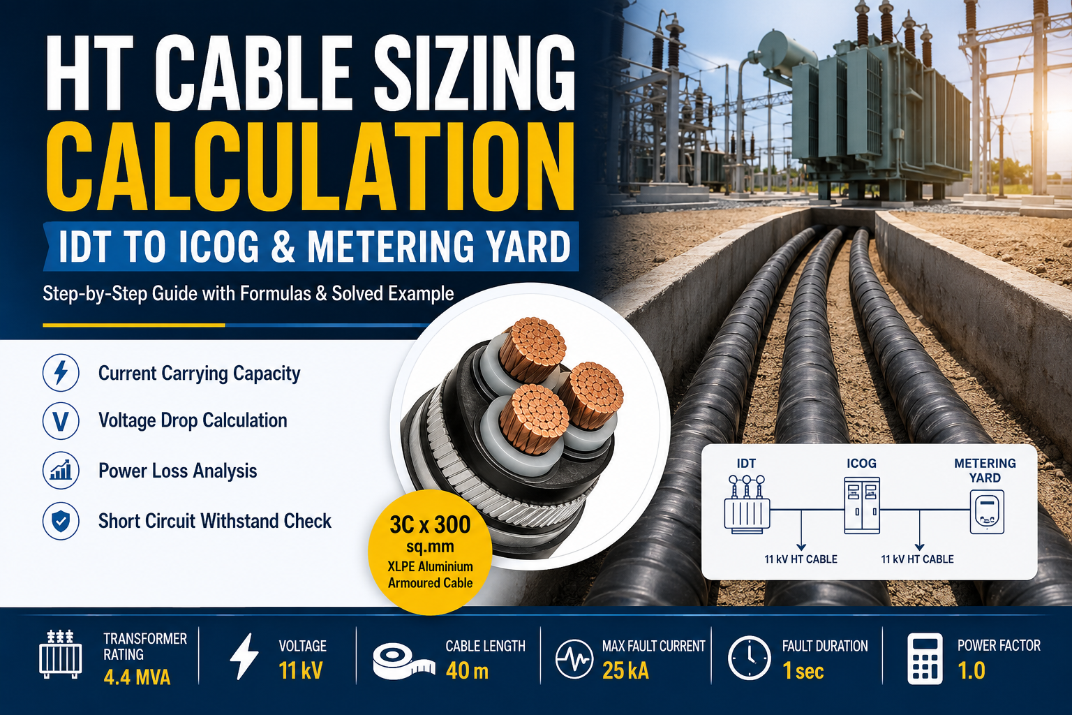
Why HT Cable Sizing for Solar Power Plants Is Important
HT cable sizing for solar power plants is an important part of electrical system design. Proper cable selection ensures safe power transmission, minimizes voltage drop and power losses, and provides adequate short-circuit withstand capability. This guide explains HT cable sizing using load current, voltage drop, cable derating factors, power loss, and short-circuit withstand calculations, with a practical example for a solar power plant.
In utility-scale solar power plants, HT cables are generally used to connect the Inverter Duty Transformer (IDT) to the Inverter Control & Output Gear (ICOG) and then to the Metering Yard. Selecting the correct cable size requires careful evaluation of current carrying capacity, derating factors, voltage drop, power loss, and short-circuit withstand capability.
This article explains the complete HT cable sizing methodology with solved calculations based on a 4.4 MVA inverter transformer operating at 11 kV.
Why HT Cable Sizing is ImportantHT cable sizing is not simply selecting a cable based on current. The selected cable must satisfy several design criteria simultaneously: Carry full-load current continuously. Operate safely under actual site conditions. Maintain voltage drop within permissible limits. Minimize transmission losses. Withstand short-circuit current until the protection system clears the fault.A cable that satisfies all these conditions ensures reliable operation and long service life.
INPUT DATA
Parameters are as follows:
Transformer Rating(S)-4400 kVA
Voltage-11 kV
Cable TypeXLPE Armoured-Aluminium
Cable Size Selected-3 Core × 300 sq.mm
Cable Length-40 m
Maximum Fault Current-25 kA
Fault Clearing Time -1 Second
Power Factor-1.0
HT Cable Sizing for Solar Power Plants: Current Calculation
HT cable sizing for solar power plants starts with calculating the full-load current of the transformer. The calculated current is then compared with the cable's permissible current-carrying capacity after considering the applicable derating factors.
Step 1 – Calculate Full Load Current
The first step in HT cable sizing is calculating the transformer full-load current.
The formula for three-phase systems is:
I=S×1000/ROOT3XV
Where:
S = Transformer Rating (kVA)
V = Line Voltage (V)
Substituting the values:
I=4400X100/1.732X11000
=230.95A
Rounded,Full Load Current = 231 A
This means the selected cable must continuously carry at least 231 A.
Step 2 – Apply Derating Factors
Cable manufacturers publish current ratings under standard installation conditions. However, actual site conditions are rarely ideal.
Therefore, derating factors must be applied.
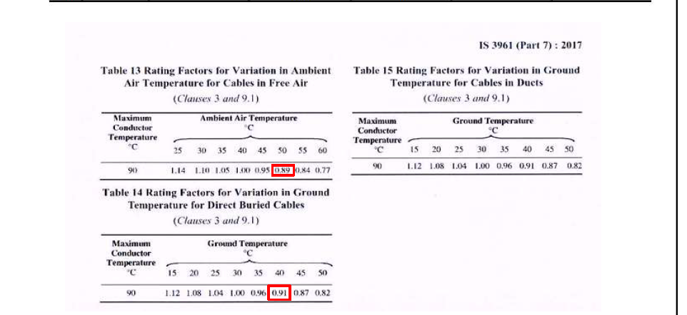
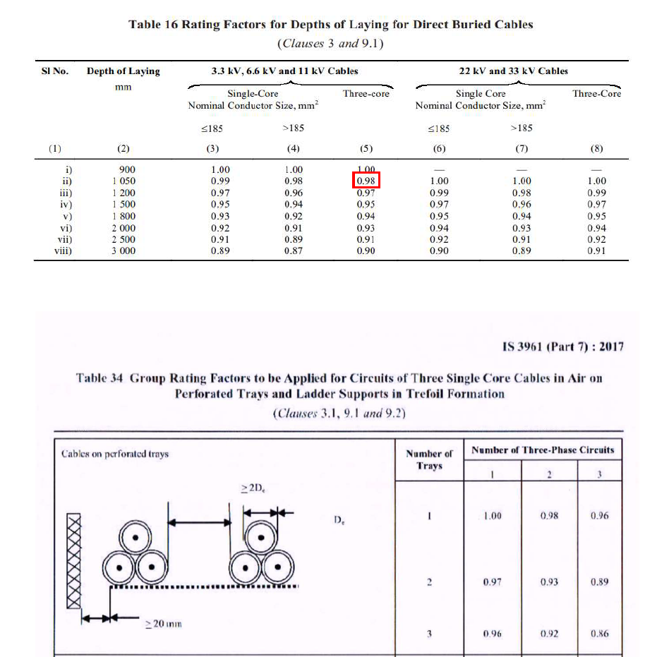
The project considers:
Ground Temperature (40°C)-0.91
Single Circuit-1
Cable Burial Depth (1050 mm)-0.98
Soil Thermal Resistivity-1
The net derating factor is obtained by multiplying all individual factors.
DF=0.91×1×0.98×1
DF=0.89
This means the cable can safely carry only 89% of its standard current rating under actual site conditions.
Step 3 – Calculate Derated Current Carrying Capacity
According to IS 3961 standards, a 3 Core × 300 sq.mm Aluminium XLPE cable has a standard current carrying capacity of: 354A
After applying derating,
Id=354×0.89(DF)
Id=315.70A
Therefore, under actual site conditions the cable can safely carry approximately 316 A continuously.
Step 4 – Determine Number of Cable Runs
The required number of parallel cable runs is calculated using:
Runs=Derated Capacity/Full Load Current
Runs=231/315.70
=0.73
Since cable runs cannot be fractional, one complete run is selected.
Therefore,Selected Cable = 1 Run × 3 Core × 300 sq.mm Aluminium XLPE Cable
The selected cable comfortably satisfies the current carrying requirement.
Step 5 – Voltage Drop Calculation
Voltage drop is another critical design parameter because excessive voltage drop reduces system efficiency and affects equipment performance.
The three-phase voltage drop equation is:
Vd=ROOT3×I×L(Rcosϕ+Xsinϕ)/1000×n
Where: Current = 231 A
Cable Length = 40 m
Resistance = 0.112 Ω/km
Reactance = 0.082 Ω/km
Power Factor = 1
cosϕ=1
sinϕ=0
Vd=10001.732×231×40×0.112/1000
Vd=1.79V
The percentage voltage drop is calculated as:
Vd%=(1.79/11000)X100
Vd%=0.02%
Most utilities allow voltage drops between 2% and 3%, therefore the calculated value of 0.02% is excellent
 Save Time on Solar Design — Get the Complete Solar Design CALCULATION WITH AUTOCAD FILES ,Click below for Design Bundle
Step 7 – Power Loss Calculation
The cable also dissipates power due to its resistance.
The power loss equation is:
PL=3I^2RL/1000Xn
PL=10003×231^2×0.112×40
PL=717.4W
Therefore,approximately 717 Watts are lost in the cable at full load.
Step 8 – Percentage Power Loss
The percentage power loss is calculated as
PL%=(717.4/4400000)X100
PL%=0.01%
A loss of only 0.01% indicates a highly efficient cable selection.
Step 9 – Short Circuit Withstand Capability
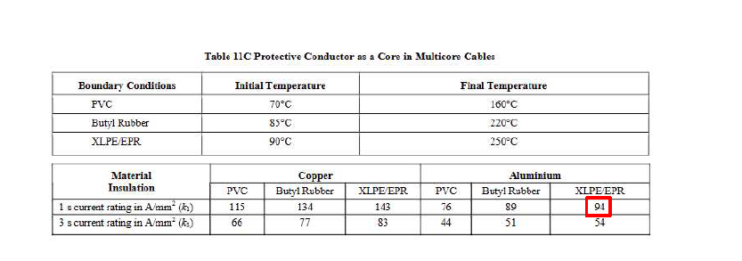
During fault conditions, the cable must safely carry fault current until the protection system trips.The minimum conductor area is determined byA=IXROOT(T)/K
Where Fault Current = 25,000 A
Fault Duration = 1 Second
Aluminium XLPE Constant (k) = 94
Substituting,
A=25000×ROOT(1)/94A
A=265.96mm2
The minimum conductor size required is therefore 266 sq.mm.
Since the selected cable is 300 sq.mm, it safely withstands the specified short-circuit current.
Conclusion;
HT cable sizing is much more than selecting a conductor based on current alone. A reliable design must account for real installation conditions, including ambient temperature, cable burial depth, soil thermal resistivity, voltage drop, power loss, and short-circuit withstand capability. By systematically evaluating each of these parameters, engineers can ensure the selected cable delivers safe operation, optimum efficiency, and long-term reliability. In this example, the 3 Core × 300 sq.mm Aluminium XLPE cable successfully meets all design requirements for a 4.4 MVA inverter transformer, making it a technically sound and cost-effective choice for utility-scale solar power plants.
Proper HT cable sizing for solar power plants ensures safe operation, acceptable voltage drop, controlled power losses, and adequate short-circuit withstand capability.