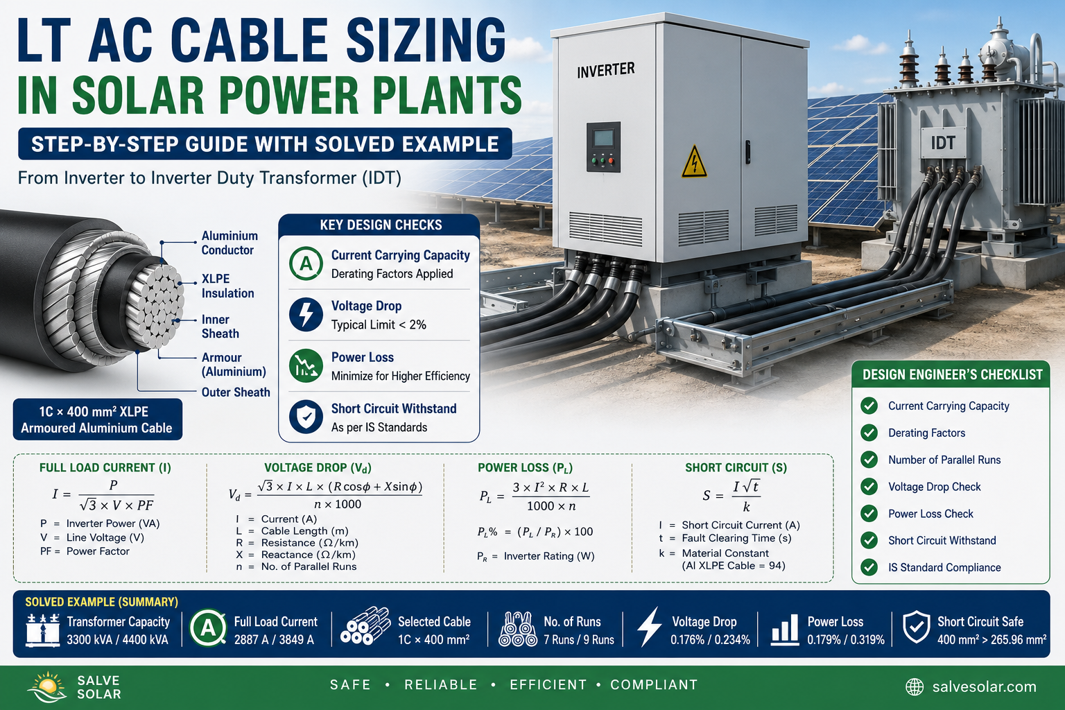
LT AC CABLE SIZING CALCULATION
LT AC Cable Sizing Calculation in Solar Power Plants is an important part of electrical design because the selected cable must safely carry the inverter output current under normal operating conditions while maintaining acceptable voltage drop, power loss, and short-circuit withstand capability. Proper cable sizing also requires consideration of installation conditions, ambient temperature, cable grouping, laying arrangement, conductor material, and applicable standards.
REFERENCES
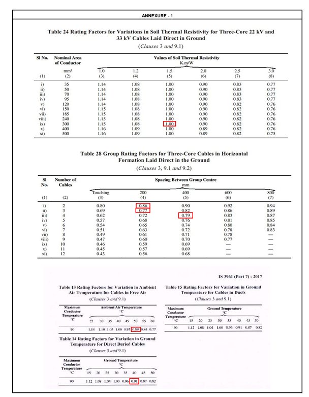
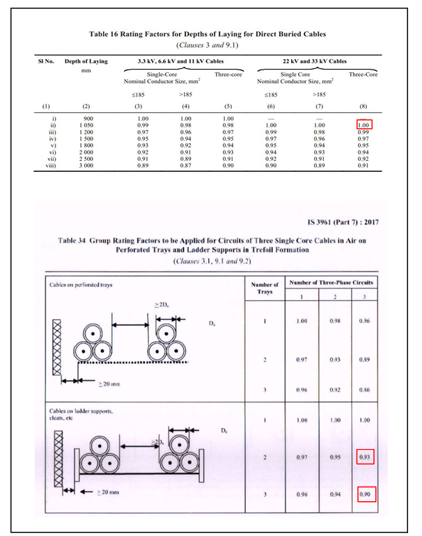
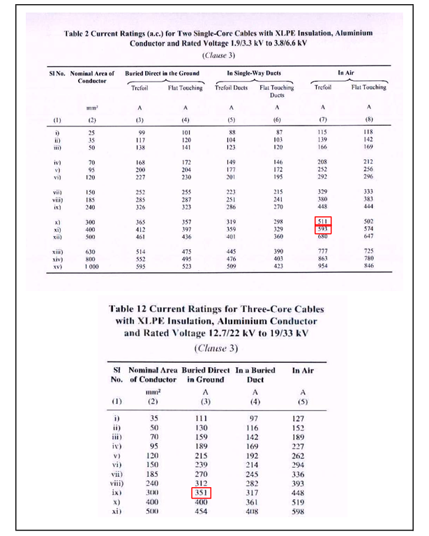
Current ratings,derating factors are taken for 1.9/3.3kV (E) LT XLPE insulated, armoured, aluminium, Power cables". (Provided)
DESIGN BASIS:
7 Circuit with 3 No of tray formation/9 Circuit with 3 No of tray formation
Derating factor for continuous current rating:
For variation in Air Temperature (Assumed 50 Deg. C.)-0.89 Refer Annexure 1 (IS-3961 Part-7)
Cables laid in Ladder type Cable trays with trefoil formation-0.9 Refer Annexure 1 (IS-3961 Part-7)
Net derating Factor = 0.89 x 0.9=0.80
Selection of cable based on Rated current carrying (continuously) capability:
Capacity of Each Trafo LV/ Each Inverter (Pr)=3300KVA
Full load current-2887A
I=P/root3×V×PF
Where:
P = Inverter Power (VA)
V = AC Voltage (V)
PF = Power Factor
Capacity of Each Trafo LV/ Each Inverter (Pr)=4400KVA
Full load current-3849A
I=P/root3×V×PF
Where:
P = Inverter Power (VA)
V = AC Voltage (V)
PF = Power Factor
Calculate Derated Current Carrying CapacityFormula
Id=Ic×DF
Where
Id = Derated Current
Ic = Cable Current Rating
DF = Net Derating Factor
Example
Cable Current Rating 593 A
Derating Factor0.80
Calculation593×0.80=474.4A
Therefore,Each 400 mm² cable can safely carry approximately 475 A.
Calculate Number of Parallel Cable RunsFormulaN=FLCI/I
Example 1
N=2887/475
N=6.08
Always round upward. Selected 7 Runs
Example 2
N=3849/475
N=8.10
Always round upward. Selected 9 Runs
Voltage Drop Calculation for LT AC Cable in Solar Power Plant
Formula
Vd = (√3 × I × L × (R cosφ + X sinφ)) / (n × 1000)
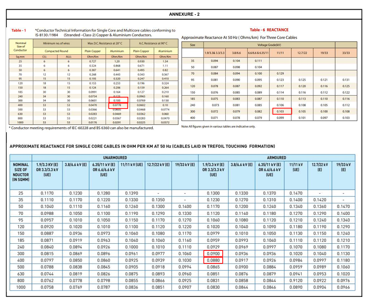
Where· Vd = Voltage Drop (V)· I = Full Load Current (A)· L = Cable Length (m)· R = AC Resistance (Ω/km)· X = Cable Reactance (Ω/km)· φ = Power Factor Angle· n = Number of Parallel Cable RunsExample from LT Cable SizingGiven:
Current (I) = 2887 A
Cable Length (L) = 25 m
Resistance (R) = 0.0778 Ω/km
Reactance (X) = 0.088 Ω/km
Power Factor = 1.0
cosφ = 1, sinφ = 0
Parallel Runs (n) = 7
Step 1: Simplify FormulaSince cosφ = 1 and sinφ = 0:
Vd = (√3 × I × L × R) / (n × 1000)
Step 2: Substitute Values Vd = (1.732 × 2887 × 25 × 0.0778) / (7 × 1000)
Step 3: ResultVoltage Drop = 1.21 V Voltage Drop (%) = (1.21 / 660) × 100 = 0.176 %
Design RecommendationFor inverter to IDT cables, voltage drop is generally kept below 2%. The calculated value of 0.176% is well within acceptable limits, indicating the selected cable is suitable.
CONCLUSION:
LT AC cable sizing calculation in solar power plants is an important part of the electrical design process because the selected cable must safely carry the inverter output current under normal and abnormal operating conditions. A proper cable selection should consider current-carrying capacity, temperature and grouping derating factors, voltage drop, power loss, short-circuit withstand capability, installation method, cable length, and applicable standards.
For a reliable solar PV system, cable sizing should not be based only on the calculated full-load current. The selected cable arrangement must be verified after applying the appropriate derating factors and it should satisfy the project's voltage-drop and short-circuit requirements. For high-capacity solar plants, the number of parallel cable runs should also be optimized to achieve a balance between electrical performance, installation feasibility, system losses, and project cost.
A properly designed LT AC cable system helps minimize energy losses, and maintain stable inverter operation, improve plant efficiency, and ensure long-term safety and reliability. Therefore, a complete LT AC cable sizing calculation should always be carried out before finalizing the cable size and installation arrangement for a solar power plant.