Introduction
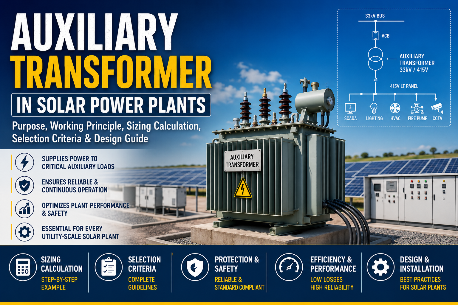
Auxiliary Transformer in Solar Power Plants is an essential part of electrical infrastructure for supplying reliable power to the equipment required for safe and continuous plant operation. It provides power to auxiliary loads such as cooling systems, SCADA equipment, battery chargers, communication systems, lighting, HVAC units, CCTV systems, fire protection systems, control panels, and weather monitoring stations.
An Auxiliary Transformer in Solar Power Plants is also known as a Station Service Transformer (SST) in many projects. It supplies electrical power to essential auxiliary loads and steps down the medium-voltage output of the solar plant to a low-voltage level suitable for powering auxiliary equipment.
The proper selection of an auxiliary transformer directly impacts plant reliability, operational efficiency, maintenance costs, and overall system availability. An undersized transformer can lead to overloading and frequent failures, while an oversized transformer increases capital cost and no-load losses.
This comprehensive guide explains the purpose, working principle, sizing calculations, selection criteria, protection philosophy, and practical design considerations for auxiliary transformers used in solar power plants.
What is an Auxiliary Transformer?
An Auxiliary Transformer is a step-down transformer installed within a solar power plant to supply electrical power to all non-generation equipment required for plant operation.
Unlike the main power transformer, which transfers generated power to the electrical grid, the auxiliary transformer supplies internal plant loads.
Typical output voltage:
415 V
433 V
440 V
Typical frequency:
50 Hz
Typical capacity:
100 kVA
250 kVA
500 kVA
630 kVA
1000 kVA
depending on plant size and auxiliary load demand.
Why is an Auxiliary Transformer Required?
A solar power plant cannot operate using only PV modules and inverters. Various support systems require continuous electrical power, including: SCADA system
Inverter auxiliary supply
Communication equipment
Lighting
CCTV
Fire alarm system
Battery charger Control room
HVAC
Water pumps
Weather station
ecurity systems
Emergency loads
Without auxiliary power, plant monitoring, protection, communication, and safety systems would become inoperative, making reliable plant operation impossible.
Auxiliary Loads in a Solar Plant
Equipment Typical load
SCADA System 2-5kw
Lighting 5–15 kW
CCTV 1–3 kW
Fire Fighting System 10–30 kW
Battery Charger 5–20 kW
HVAC 20–80 kW
Water Pumps 20–150 kW
Inverter Cooling 30–150 kW
Communication System 2–10 kW
The sum of these loads determines the auxiliary transformer rating after applying diversity and future expansion factors.
Working Principle of an Auxiliary Transformer
The auxiliary transformer operates on the principle of electromagnetic induction, where alternating current in the primary winding creates a magnetic flux in the transformer core. This changing magnetic flux induces a voltage in the secondary winding proportional to the turns ratio.The relationship between primary and secondary voltage is:
Vp/Vs=Ns/Np
where:
Vp = Primary Voltage
Vs= Secondary Voltage
Np = Primary Turns
Ns = Secondary Turns
For example, an 11 kV/415 V auxiliary transformer reduces the medium-voltage supply to a low-voltage level suitable for plant equipment.
Auxiliary Transformer Sizing Calculation
Transformer sizing begins by identifying every auxiliary load in the plant.
Step 1:Prepare the Load List
Equipment Load (kW)
HVAC 45
Lighting 12
SCADA 5
Fire Pump 75
Battery Charger 10
CCTV 3
Communication 2
Water Pump 35
Total Connected Load = 187 kW
Step 2: Apply Diversity Factor
Not all loads operate simultaneously.
Assume:
Diversity Factor = 0.85
Demand Load:187 × 0.85 = 159 kW
Step 3: Apply Future Expansion
Future Expansion = 20%
159 × 1.20 = 191 kW
Step 4: Convert kW to kVA
kVA=kW/Power Factor
Assume PF = 0.9
191/0.9=212 kVA
Step 5: Select the Next Standard Rating
Available transformer ratings:
200 kVA
250 kVA
315 kVA
500 kVA
Selected Rating = 250 kVA
Selection Criteria:
When selecting an auxiliary transformer, engineers should consider:
Total auxiliary load
Demand factor
Diversity factor
Future expansion
Voltage level
Short-circuit withstand capability
Cooling method
Efficiency
Impedance
Installation location
Ambient temperature
Harmonic loading
Applicable IS/IEC standards
Difference Between Auxiliary Transformer and Power Transformer
Parameter Auxiliary Transformer Power Transformer
Purpose Supplies plant auxiliary loads Transfers generated power to the grid
Capacity 100–1000 kVA Several MVA
Output Voltage 415 V 11 kV, 22 kV, 33 kV, etc.
Load Type Internal plant equipment Grid export
Conclusion:
The auxiliary transformer is a vital component of every solar power plant, providing reliable low-voltage power to the systems that keep the facility operating safely and efficiently. Proper sizing requires a systematic evaluation of connected loads, diversity, future expansion, voltage levels, and protection requirements. Selecting the right transformer enhances plant reliability, minimizes operating costs, and supports uninterrupted operation throughout the project's life cycle.
For your next sections, I recommend adding professional illustrations, including a featured image, a labeled auxiliary transformer diagram, a single-line diagram (SLD), and calculation flowcharts to make the blog more engaging and technically valuable.