Solar Array Layout Design Principles
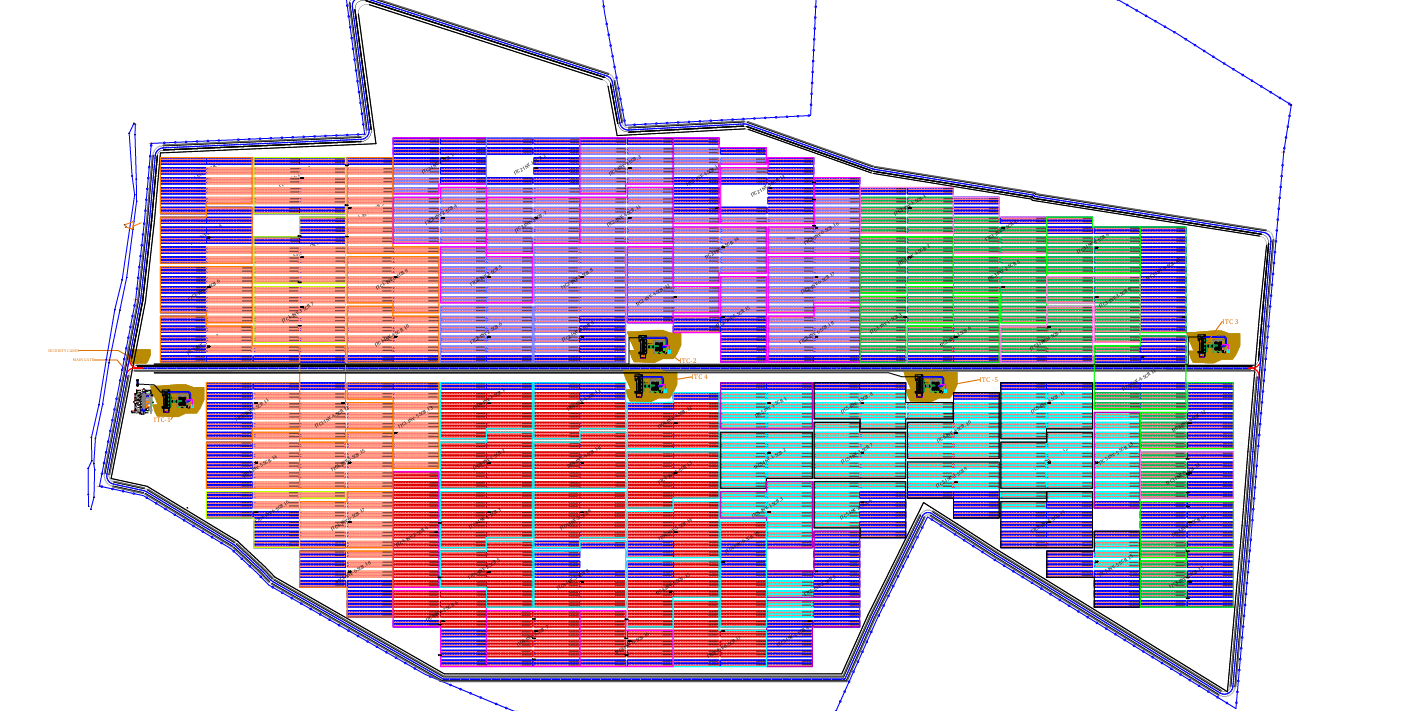
Solar Array Layout Design is one of the most critical stages in the engineering and development of a utility-scale solar power plant. A properly designed Solar Array Layout ensures maximum energy generation, efficient land utilization, lower construction costs, easier operation and maintenance, and long-term system reliability. During the design process, engineers must consider several technical, environmental, electrical, and civil engineering factors to achieve the optimum balance between energy production and project cost. A poorly planned layout can lead to shading losses, excessive cable lengths, difficult maintenance access, drainage issues, and reduced overall plant performance.
Solar Array Layout optimization is one of the most important steps in designing a utility-scale solar power plant. A well-planned Solar Array Layout increases energy generation, reduces shading losses, optimizes land utilization, and lowers project costs.
Step 1: Collect Design Inputs
Before starting the layout, collect all project information.
Required Inputs :
-Topographic Survey (DWG)
-Boundary Coordinates
-Contour Levels
-Civil Drawings
-Geotechnical Report
-Module Datasheet
-Inverter Datasheet
-Transformer Location
-HT Line Location
-Road Layout
-Drainage Layout
-Client Design Criteria
Step 2: Study the Site
Understand the land completely before placing modules
-Check Site Boundary
-Slope Direction
-Existing Roads Trees
-Buildings Rivers,Ponds
-High Tension Lines
-Utility Easement
-Flood Area
-Rocky Area
Step 3: Decide Module Orientation
There are two common orientations.
Portrait
-Easy cable routing
-Better natural cooling
-Less mounting rail
Landscape
Better wind resistance
Lower table height
Used in tracker systems
Choose based on
Wind Load
Structure Type
Manufacturer Recommendation
Step 4: Select Table Configuration
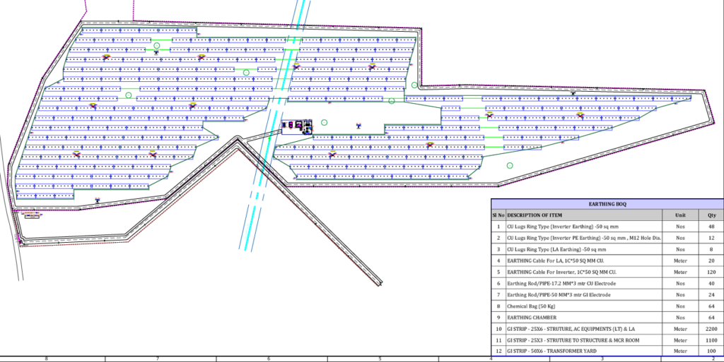
Check string configuration (No.of modules per string)
Examples:
2Px28-2 PORTRAIT (28 modules per string)
Module = 620W
Configuration = 2P × 28
Total Modules/Table
2 × 28 = 56 Modules
Step 5: Determine Tilt Angle
Tilt depends upon
-Latitude
-Annual Yield
-Structure
-Cost
-Wind Load
PVsyst optimization should be performed.
Step 6: Calculate Row Pitch (Inter-row Spacing)
Formula
Pitch = Vertical Height / tan(Solar Altitude)
Where,
Vertical Height:
H = Module Length × sin(Tilt)
Step 7: Keep Required Maintenance Roads.
Maintenance roads are essential in a solar PV plant to ensure safe construction, efficient operation, and quick access for maintenance activities. Properly planned roads allow personnel, cleaning vehicles, cranes, and emergency equipment to reach every section of the plant without damaging the solar arrays.
Why Maintenance Roads Are Important:
Provide access for installation and commissioning.
Enable routine inspection and preventive maintenance.
Allow module cleaning vehicles to move throughout the plant.
Facilitate replacement of modules, inverters, and transformers.
Ensure emergency vehicles can reach any location in the plant.
Reduce maintenance time and operational costs.
Main Access Road
width-6–8 m, Entry for heavy trucks, cranes, and construction equipment
Internal Maintenance Road
width-4–6 m, Daily access for maintenance vehicles and personnel
Emergency Road
width-6-8m,Access for fire trucks and emergency response vehicles
Conclusion
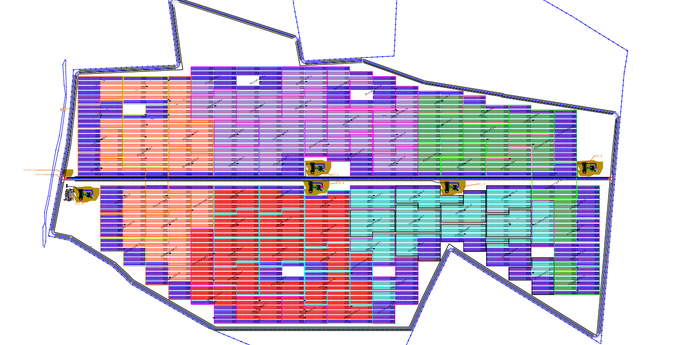
Optimizing a solar PV array layout is much more than fitting the maximum number of modules within a site boundary. A well-designed layout balances energy generation, construction cost, cable routing, maintenance accessibility, safety, and long-term operational efficiency. By carefully evaluating site conditions, selecting the appropriate module orientation and table configuration, optimizing row spacing, planning maintenance roads, minimizing cable lengths, and validating the design through simulation tools such as PVsyst, engineers can significantly improve the overall performance and profitability of a solar power plant.Whether designing a small commercial installation or a multi-megawatt utility-scale project, following a structured array layout optimization process helps maximize energy yield while reducing installation and maintenance costs. Investing time in proper planning during the design stage leads to a safer, more reliable, and more cost-effective solar PV system throughout its entire lifecycle.
Professional Tips Used by EPC Companies:
Start module placement from the longest straight boundary to maximize module count.
Keep all tables aligned in one direction for easier installation.
Group arrays by inverter capacity to simplify stringing.
Minimize odd-shaped tables at boundaries. Align roads with inverter stations to reduce cable trench complexity.
Follow natural contours to reduce grading and earthwork costs
Reserve expansion space for future plant capacity increases.
Validate the layout in AutoCAD before importing to PVsyst.
Optimize for the lowest Levelized Cost of Energy (LCOE), not just the highest module count.